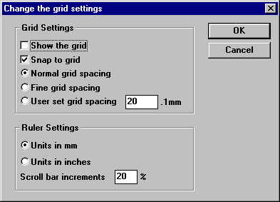
- Show Grid
Options Menu Reference
Settings

-
Show Grid
This causes the grid to be displayed.
If the grid is too fine to show at the current zoom then it will not be displayed. To see the grid zoom in.
If the fine grid is enabled then the points which lie on the normal grid as well are shown as crosses.
- Snap to Grid
This option should under normal conditions be selected.
This option makes any mouse position snap to the nearest point on a grid. This allows the easy alignment of objects. It also ensures when you attempt to connect a wire to a symbol that the connection is made correctly. For this reason snap to grid should always be on.
If the snap to grid feature is turned off then when you attempt to connect a wire to a symbol it is very difficult to ensure both the end of the wire and symbols connection point are on the same point. With snap to grid this is made easy. If they are not on the same point, not only does it look untidy when printed but it will also be considered un-connected by the special tools.
- Normal, Fine, User grid spacing
In most cases you will wish to use normal grid spacing. A fine grid has twice as many points to a normal grid and is especially useful for annotating a design and drawing symbols.
If you wish you may specify your own grid spacing by entering the spacing in the dialog box. You may enter the units in inches or mm, depending on the Units setting (as described below).
- Units in mm or units in inches
This defines which units are used by the whole program inches or mm. The ruler and show position dialog will reflect the changes.
- Scroll bar increments
This determines by how much the design will be scrolled when the arrows at the side of each scroll bar is clicked.
Colours
This option will cause a dialogue box to be displayed with the current colours in use by the current design. If you wish to change any of the colours for the objects shown, simply click on the colour and then select a new one. This will change the colour for that object in the entire design. Currently you may change the colours of: wires, junctions, no-connects, buses, pins and power elements.
If you wish to return the colours to the TinyCAD default, select the “defaults” button in the dialogue.
Show Position
This option will cause a dialogue box to be displayed with the current co-ordinates of the mouse pointer in the design.
The position is displayed in either inches or mm depending which units are selected by the Grid Settings option in the Options menu.
To remove the dialogue box select this option again.
Snap to Grid
Turn the snap to grid on or off. This is a short-cut for the same option in the Grid Settings dialogue.
Repeat Directions
This option is a sub-menu with options for the repeat command, and options for use when placing labels, text and placing pins.
The Up, Down, Left, Right options specify where an object is placed when it is repeated.
The Name Increment/Name Decrement options specify how label names, text or pin names are altered after they are placed.
The Pin Increment/Pin Decrement options specify how the pin numbers are altered after placing a pin. Note that you can only place pins when editing a library symbol.